In this post I will document my journey of building a Eurorack sequencer from scratch. I will try to be as detailed as possible and include all the steps I'm taking. I will also try to include all the resources I'm using and all the mistakes I'm making. I hope this will be helpful for someone out there.
For the impatient: find the code here
Why?
I'm doing this, mostly because I think it's going to be a lot of fun and I'll be learning a lot lot of things on the way. My goal is to gain knowledge in all the steps involved to (figuratively) put a module into the shelves starting from nothing at all. I think when it comes to engineering (electronics) the Pareto Principle applies. You can build a "working" prototype on the breadboard in 20% of the time (maybe even less). To get to a product that other's wouldn't mind using it takes a lot of effort, that I don't really take most of the time. When I'll get to 20% I call it "basically done" and move on to the next thing.
Not this time.
I know this is not uncommon in the SynthDIY world, but it's new for me. The module I am setting out to build should be a fairly simple step-sequencer with some key-features:
- Precise(-ish) timing (not really a feature but I guess it'd be useful)
- Fader controls with LEDs (the Metropolis really impressed me)
- Simple quantizer (Major and Natural Minor, maybe adding more as I go)
- V/Oct and Trigger output
- 2 output channels (yeah this might be debatable)
- Clock/Trigger input (I think I'm already regretting this one)
In order to get to a fully fledged module I have to learn (or at least understand)
- How sequencers work (duh)
- How Eurorack modules are laid out (power / CV standards)
- Enough music theory to figure out how to do quantizing
- Electronics (circuits and parts)
- Understand microcontrollers (and selecting the right one for the job)
- Programming C/C++
- Creating schematics with KiCAD and building them out into boards eventually creating GERBER files
- Creating a template for the panel (using whatever software is necessary for that)
- Operating a laser cutter
and probably much, much more.
This sounds like a lot and as far as I'm concerned right now it also is. But I feel determined and would like to share my progress within that journey with everyone interested. I found it hard to find good resources describing the whole process, so I thought I'd share and maybe it'll be helpful for one or the other. From now on I'm hoping to be able to update this post every week with the current state of the project, leaving out nothing and especially noting the struggles, problems and drawbacks I will (inevitably) encounter.
If you want to follow along, buckle up, it's gonna be a wild ride.
A little bit concerning my background. I went to university once, studying electrical engineering - though rather focusing on the biiiiig electronics. Power plants and high voltage power transmission and stuff. Furthermore I've been working as a web-developer for about 5 years now. Some of my knowledge might come in handy throughout this endeavor.
Build log
Week 1-4 (sometime April - May 2020)
Yeah, I cheated a bit, summarizing all the first weeks but I just decided to publicize this, so here we are.
Starting out
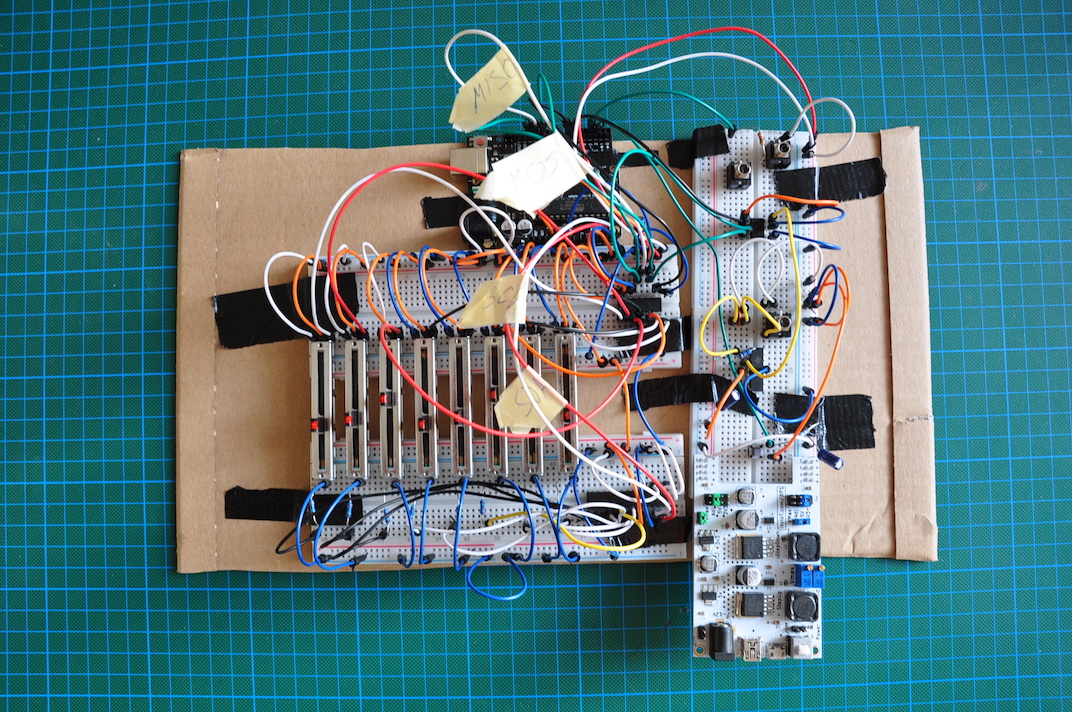
I began with smashing together a prototype, loosely based on the midi2cv project by Larry McGovern and a few components I had lying around. This is the first time I dip my toes into building modular synth or Eurorack stuff, so I just wanted to get a very simple thing going by generating a V/Oct signal and a trigger.
So I hooked up an Arduino Uno with a DAC (Digital to Analog Converter) and started tinkering. You will find the code and schematics for this here.
Generating a V/Oct signal
The first challenge is to generate a signal that adheres to the 1V/Oct standard that all (?) Eurorack modules adhere to. The Wikipedia page turned out to be quite resourceful. Using the MCP4822 DAC and the LM324N quad-op amp (I'll talk about them more later) as in the Midi2CV circuit we can span 8 Octaves. I used the definition in the table on the Wikipedia page putting A0 at 0V and A8 at 8V. Now that's settled let's take a look at how to generate the actual signal. The MCP4822 DAC has a 12-bit resolution and can output voltage values between 0 and 4.096 mV. That's not enough to cover the whole 8 octave range (we would need 8V for A8), so we need to amplify that using an op-amp (LM324).
We are putting out \( \frac{4095mV}{87} = 47.069mV \) per note and \( 12 \times 47.069mV = 564.828mV \) per octave. That needs to be scaled up properly. This means we need to generate a scale factor of \( \frac{1V}{564.828mV} ≈ 1.77 \). This is the gain we need to generate with our op-amp. In the circuit used here we have a non-inverting amplifier circuit with a gain of
$$1 + \frac{R1}{R2} = 1 + \frac{7.7kΩ}{10kΩ}.$$
See also the wonderful Analog Engineer's Circuit Cookbook on page 14.
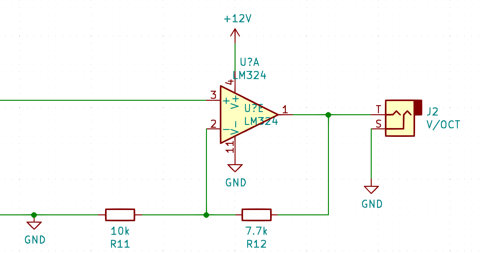
The signal on pin 3 of the op-amp comes from pin 8 (channel A out) of the DAC output.
The Op-Amp also has to be fed a supply voltage of at least around 10V (it can output a voltage that is at max the supply voltage minus some losses as it's not an ideal op-amp of course).
Let's look at some code:
  unsigned int command = channel ? 0x9000 : 0x1000;
  command |= gain ? 0x0000 : 0x2000;
  command |= (mV & 0x0FFF);  // Limit to 12 bit (max 4096)
We're setting the command to use a specific channel of the op-amp (we just use 0 in our case) and whether it should use the gain of 2 (yes, we want that to be able to output 4096mV, otherwise only 2048 are possible). The command has to be structured this way as we are writing to certain registers of the DAC via SPI. This is a somewhat lengthy, tedious learning process (at least it was for me). If you would like to know how that works exactly, drop me an email. and I happily write about it. All the information needed can be found in the datasheet. I also left some (helpful?) comments in the code which show how the command is assembled.
Using this setVoltage command we can now "play" arbitrary notes on a V/Oct calibrated device. Nice!
Adding some fader action
Next step was to add some faders with LEDs to the game. I got eight Bourns slide potentiometers with LEDs from mouser and wired them all up:
As the Arduino doesn't have enough analog inputs (I need at least 8!) I used an MCP3008 I had lying around to read the analog values of the faders. This is also done via SPI (see this function). I'm not going into detail here as I plan to replace this soon, directly using the analog inputs of the Microcontroller I will end up using (yes, spoiler: I will ditch the Arduino). If you're interested how to sample potentiometers with the MCP3008, go check out https://rheingoldheavy.com/mcp3008-tutorial-02-sampling-dc-voltage/. They are explaining it much better than I could.
The LEDs in the sliders are pretty standard. I wired them up with ~200Ω resistors and used an MCP23017 as a GPIO expander to add some digital pins to the Arduino. I don't know whether that was necessary and in the future I will also use GPIO pins of the MCU directly for this, so I won't go into too much detail here either.
Arduinoooooooo a.k.a. Timers and other Adventures
In my first approach I just used delay(ms) to move to the next step after a given amount of time ( \( \frac{60}{bpm} \times 1000 \), in ms to be precise). There's a lot of information out there about why that is not a great idea and why it's best to use timers for that (tl;dr: delay() makes the whole MCU sleep for that amount of time and won't be able to register any input or, in fact, do anything else). To get started with Arduino timers I recommend these four videos:
- Level Up Your Arduino Code: Registers
- Level Up Your Arduino Code: External Interrupts
- Level Up Your Arduino Code: Timer Interrupts
- Electronic Basics #30: Microcontroller (Arduino) Timers
I rewrote the timer code and created a Metronome class to take care of all that: metronome.cpp
Here's how it works:
The Begin function sets up all the registers to use an output compare interrupt, which will trigger every time the timer has counted up to a specific number (see the videos for more details). We also reset the timer count to 0 once it has reached the number. This number is calculated in the SetBPM function and wrote into the OCR1A register, as we are using the 16-bit Timer/Counter1:
$$OCR1A = \frac{f_{cpu}}{s_{prescale}} \times \frac{60s}{bpm} = \frac{16000000\frac{1}{s}}{256} \times \frac{60s}{bpm}$$
where \( f_{cpu} \) is the Arduino's frequency (16MHz).
See also the datasheet, "16-bit Timer/Counter1 with PWM" (the most important section would be the register descriptions there).
In line 85-87 we set up the interrupt service routine, setting the internal _tick variable to true. This is utilised by the Tick() function in the main loop() to determine whether in this loop a metronome tick happened.
Using the 16-bit timer and a prescaler of 256 we can expect a maximum deviation of 8μs per beat (depending on the bpm) which amounts to roughly 1,5s per day. I think that's fine enough for now.
A quantizer quantizes
In the first version of the code I also included a simple quantizer which can quantize the set notes to any major or natural minor scale. So how does it work? Quantizing is essentially the limitation of the available notes to a certain set. This could be (and is in my case) a certain key. First we list out all the notes in the chromatic scale (all 12 of them):

(from Wikipedia)
#define NoteA 0
#define NoteA_ 1
#define NoteB 2
#define NoteC 3
#define NoteC_ 4
#define NoteD 5
#define NoteD_ 6
#define NoteE 7
#define NoteF 8
#define NoteF_ 9
#define NoteG 10
#define NoteG_ 11
where notes with the underscore _ at the end are sharps. See here.
In the quantizer itself we can then set the tonic (the note we start the scale with), the key (major or minor natural) and the octave we would like to start in.
We define the two step patterns for major and minor natural scales. Whole steps are a 1 and half steps are a 0:
Major

(from Wikipedia)
bool majorScale[7] = {1, 1, 0, 1, 1, 1, 0};
Minor

(from Wikipedia)
bool minorScale[7] = {1, 0, 1, 1, 0, 1, 1};
We could do this for all (most) of the scales out there but this is what I wanted to start with.
Then, in the refresh() method of the quantizer we go through this pattern and create two arrays of notes and the corresponding octaves (we have to jump an octave - by our definition - when starting a scale on a note that's not A). If the current step is a minor step we go up one semitone, if the current step is a major step we go up an additional semitone.
That yields something like this
uint8_t notes = {NoteE, NoteF_, NoteG_, NoteA, NoteB, NoteC_, NoteD_};
uint8_t octaves = {1, 1, 1, 1, 1, 2, 2};
when starting on E1 for a major scale.
We use these arrays to limit (or scale) the range of the potentiometer to these. See lines 270-272 where we determine the fader position and get a voltage for the V/Oct DAC corresponding to the fader position and the quantised notes and octaves.
Shifting everything
I decided to add a shift button to use the faders for other settings as well. These lines describe how the interface logic should work to change values of tonic (fader 1), octave (fader 2), key (fader 3) and bpm (fader 4). I wanted it to only apply the changes when you actually move a fader and not when you just press shift. That's where all these prevous...Position variables come into play. It's super messy and there must be a better way but this is a prototype after all.
Adding a trigger
A trigger is relatively simple to integrate. As the Arduino is switching with 5V we can utilize a digital pin which we set HIGH for a short period of time (about 50ms) and then to LOW again. We feed this signal directly into a jack to connect to external gear.
Baby-steps with KiCAD
Not much to report here except for some results. I decided to try out KiCAD for building the schematics and the board-layouts as it is free and open source (yay!). I wanted to be able to conserve the state of the breadboard mess somehow so I created a schematic for the current state.
It roughly looks like this (sorry for the big image):
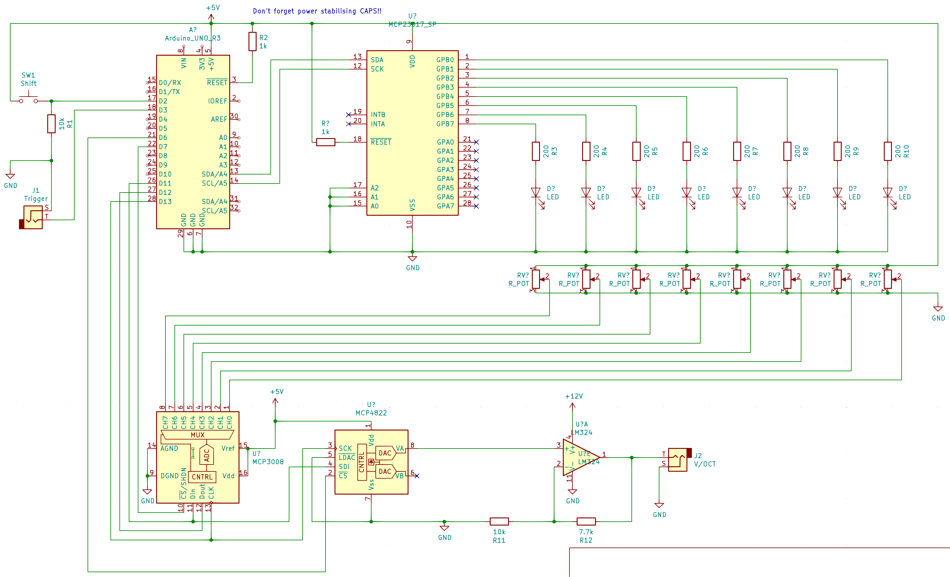
It's not done yet and missing a lot of labels and probably some other really important information but I'm just starting out and will add that later (when I do the revised version).
Switching to ARM (wohooooo)
tbd
Connecting external inputs
I wanted to be able to accept external inputs (like a clock trigger or gate) and looked at how others do it. Naturally I reviewed the circuits of Mutable Instruments modules first.
Detecting whether a plug is plugged into a jack
This lead me down quite some rabbit hole. An audio jack has a pin that is normally connected to the signal pin but when a plug is plugged in it is being disconnected. You can detect this missing connection. But how? First I looked into the MI code and schematics and found that all the outputs use a so called "Normalization Probe". This technique just uses one GPIO pin of your MCU to detect which jacks are plugged in. It sends a pseudorandom signal into the detect pins of all of the jacks and tries to detect this signal on the signal line of the jack (as these are connected when nothing is plugged in). The jacks on which this signal is not detectable should be plugged in. This was a bit too complex for the use case of just detecting one jack plug. So I went down a different path. I looked around and eventually found this article: Using comparators to detect accessories in portable audio applications.
The paragraph under the first sub-headline describes a simple circuit to detect the presence in a jack.I sketched that out a bit and came up with this:
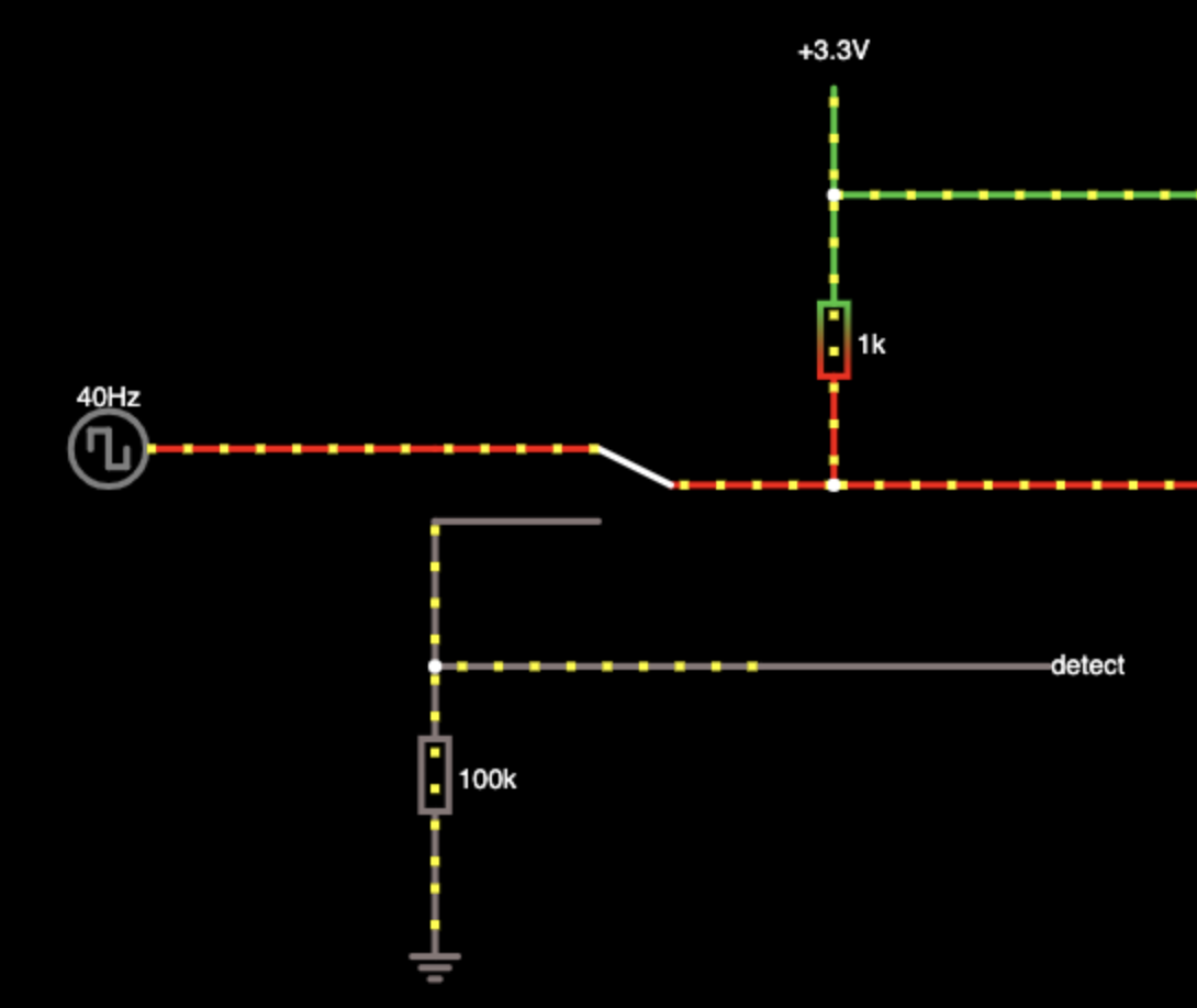
The 40Hz voltage source should resemble the input signal whereas the switch is either connecting the signal with the internal signal line (top position) or the detect pin with the internal signal line (bottom position). When the switch is in the top position (plugged in), detect is pulled to ground, in the other position it's pulled up. We can measure the detect line using a GPIO pin and react accordingly (HIGH is no plug, LOW is plugged in).
Normalizing the input signal
There's no real standard for trigger inputs so the voltage can vary quite a bit. We're just interested in the transients of gates (or any kinds of signal, really) above a certain threshold. This circuit accomplishes the normalization.
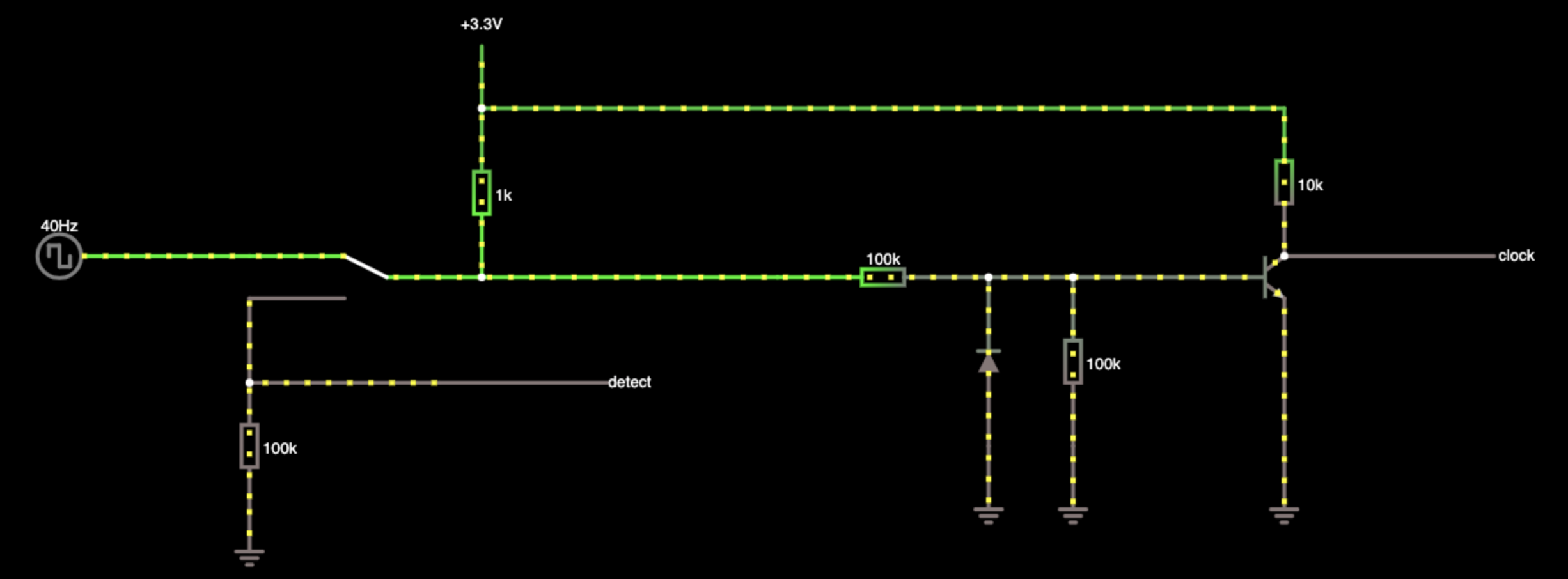
Ignore the plug detection parts for now. This circuit converts any kind of signal into a 3.3V gate which is HIGH when the signal passes a certain threshold. This threshold is determined by the transistor characteristics and the horizontal 100k resistor which influences the current into the transistor base. We measure the clock signal at the transistor's collector which is pulled to 3.3V when the transistor is "off" and pulled to ground when the transistor is "on". That means if we have a sufficiently high current at the base (input signal HIGH), the clock signal will be LOW and the other way round. That means our measured gate signal will be inverted (and within our 3.3V measuring range). The diode prevents negative spikes to be seen by the transistor and the 100k resistor next to it pulls the base to ground in case there is no cable plugged in or it is floating.